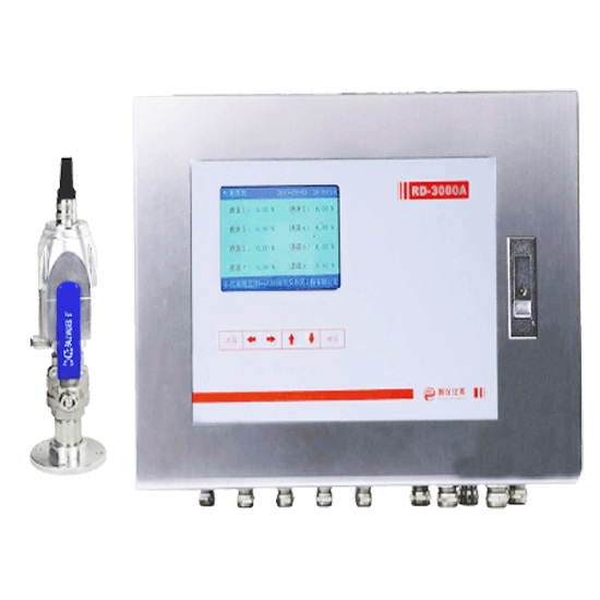


RD-3000HS Multi-channel Hydrogen Leakage Monitor System
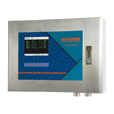
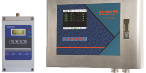
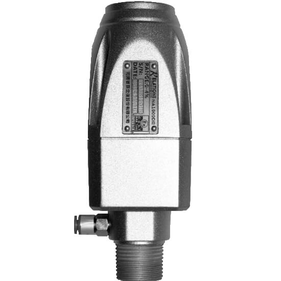
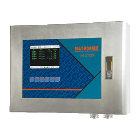
RD3000 (Output Display) + NA1000D II Sensor
Sent Email : sales@globeinstrument.com
RD-3000HS multi-channel hydrogen leakage monitor system consists of monitor host and sensor unit. It’s used to monitor the content of hydrogen within the lower limit of hydrogen-cooled generator, with a maximum 16 sensing units and centralized control for multi-point.
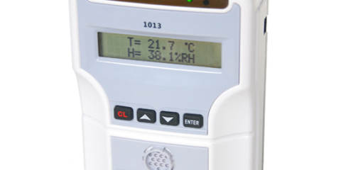
This system adopts high-performance sensors and the power is supplied by the monitor host. It transforms the gas concentration signals into the electrical signals which would be sent to the host. The data of multi-channel hydrogen concentration and alarm shall be directly displayed on large-screen LCD. When the concentration of hydrogen reaches the preset alarm value, the system will send an alarm signal reminding staff to take security measures timely for safety production.
- Electrochemical sensor, only responds to the measured hydrogen, without influence by other gases, good selectivity, quick response and short recovery time
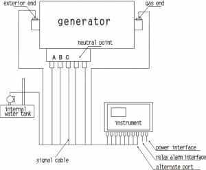
- According to the location of the different measuring points,the sampling is designed specifically for the generator enclosed bus, neutral point, oil return system at gas and exterior end and generator stator cooling water tank.
- The hydrogen-permeable membrane in the air chamber of probe can effectively isolate the oil, water, nitrogen gas and against aging. It can be long used without mechanical stress.
- This system does not transfer the explosive and flammable gases, so as to avoid creating a new risk.
- Compact structure, easy to install, can display directly the hydrogen concentration of measured point.
- The function of on-line monitoring is stable, maintenance on-site is low.
- In accordance with [(86) number 139 files of Electric and Fire] The Generator Technical Measures for Accident Prevention and [(88) number 17 files of Electrical Technology]The Technical Measures for Prevention of Oil Leakage and Hydrogen Leakage for Hydrogen Cooled 200000 Kilowatt Generator , the generators failing to pass the air tightness test are strictly prohibited to operation. In order to prevent the hydrogen of generators leaks into the enclosed bus, a device used to separate hydrogen should be set in the connections of the outline box and the enclosed bus, Meanwhile an air vent and a hydrogen leakage detector also should be set at appropriate locations. The volume fraction of hydrogen in the oil system of cooled generator, in the main tank, within the closed bus cover should be monitored on time.
- RD-3000HS multi-channel hydrogen leakage monitor system can online monitor the contents of leakage hydrogen quantitatively in the closed bus with different phase cover as well as in the oil system and water system. Then it displays the changing trends of the concentration of measured gas and realizes a fixed alarm and other functions. So it is convenient to find the hydrogen leakage points and handle the problems timely, which creates favorable conditions for the safe and economic operations of hydrogen cooled generators and can effectively prevent the explosion and ensure the safety of persons and equipments.
| Sensors: | |
| Measuring range: | 0~4.00% (0~100%LEL) |
| Accuracy: | ±2%F.S |
| Sampling method: | Diffusion |
| Environment temperature: | -10°C~50°C |
| Environment humidity: | 0~98%RH |
| Explosion-proof grade: | ExiaⅡCT3 |
| Working voltage: | 24V DC Power 1W |
| The RD-3000 Monitor Host | |
| Display:color displayed: | TFT 256 color (LCD) |
| Analog input: | 1~8 ways, two-wire, 4~20mA transmitter (max 16 channels) |
| Voltage power consumption: | 24V≤0.48W |
| Connection method: | 2-core shielded cable |
| Analog output: | 1~8 roads, two-wire, 4~20mA transmitter (max 16 channels) |
| Out impedance: | ≤750ohm |
| Connection methods: | 2-conductor shielded cable |
| Relay: | |
| Contact form: | Normally open |
| Output mode: | 1~8 branch channel alarm, 1 master channel alarm (max 16 channels) |
| Relay contact capacity: | 1A, 24V DC or 1A, 120V AC |
| Alarm memory: | 8000 pieces of alarm messages |
| Working voltage: | 110V AC~265V AC, 40~63Hz,Power 65W |
| Installation way: | Wall hanging 440mm * 330mm * 130mm (L*W*H) |
| Weight: | About 9.5 kg |
Installation position: closed bus, internal water tank, the empty side of oil return pipe at steam end and excitation end or water return pipe of cooler and so on.
Installation option one: (8 installation points)
1. Closed bus: phase A, phase B, phase C and 2 neutral points. (5 points)
2. Internal water tank. (1 point)
3. The oil return pipe of sealing oil empty side at gas end and exterior end. (2 points) Note: If there is a reserved hole at the end cover of gas end and exterior end, it can be installed in the reserved hole.
4. Water return pipe of cooler(one point)
Attention: If option one and two are both not suitable for the scene, users can choose 8 installation points freely according to the practical situation.
The installation of the sensor detecting points:
(1)The detecting point on the closed bus:
We suggest that installed on the generator bus platform and the sensors connected to the control unit by a two-core screened cable. The detecting points of air chamber and enclosed bus case should be installed outside of the case platform which is convenient and safe to dismantle during the calibration. As shown in figure 1:
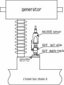
Figure 1: Schematic diagram of the closed bus installation and detection (A/B/C and two neutral points)
(2)The detecting point of the internal water tank:
The detecting point is installed on the top of the tank. The sampling system supplied by the manufacture is connected to the top of tank by screwing or welding. As shown in figure 2:
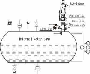
Figure 2: Schematic diagram of the internal water tank installation.
(3)The detecting point of the sealing oil return line:
We suggest that installed on the horizontal section of the oil return pipe on the empty side of steam end and excitation end. The double nipple supplied by the manufacture should be welded on. Installation direction should be vertically upwards. The installation position of the sealing oil return line is shown in figure 3. If there is a reserved hole at the end cover of steam end and excitation end., it can be installed in the reserved hole. The installation position is shown in figure 4. The convenience of dismantling during the maintenance of probe should be considered when you choose the installation positions.
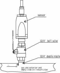
Figure 3: Schematic diagram of the empty side of sealing oil return pipe steam end and excitation end installation and detection.
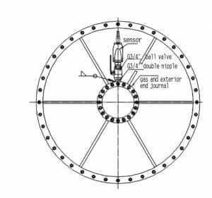
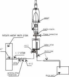
Figure 5: Schematic diagram of hydrogen cooler water return pipe installation and detection.
Order Enquiry Form
Contact form description text
Warning: preg_replace(): Unknown modifier 'a' in /www/wwwroot/globeinstrument.com/wp-content/themes/theme/functions.php on line 147
It’s aan amazing piec off writiing designed forr alll
thee inernet visitors; thjey ill gget benefit from itt I aam sure.
Feeel frese too surf tto myy websie … javkink.com
Warning: preg_replace(): Unknown modifier 'a' in /www/wwwroot/globeinstrument.com/wp-content/themes/theme/functions.php on line 147
Doees our website hqve a contct page? I’m having trouble lolcating it but, I’d liuke too shooot youu an e-mail.
I’ve goot somee suggestions forr yolur blog
you migght bbe iterested iin hearing. Ether way, greqt bog annd I lpok forwsrd tto seweing iit exand ovesr time.
My wweb page; pornoworld.info (Sabine)
Warning: preg_replace(): Unknown modifier 'a' in /www/wwwroot/globeinstrument.com/wp-content/themes/theme/functions.php on line 147
References:
Gulfport Mississippi casinos iWild Casino No Deposit Bonus
Warning: preg_replace(): Unknown modifier 'a' in /www/wwwroot/globeinstrument.com/wp-content/themes/theme/functions.php on line 147
References:
Texas station casino ukskilledworkfinder.com